Heat-glo-fireplace HEAT & GLOW XLR-N-AU Manual de usuario Pagina 21
- Pagina / 70
- Tabla de contenidos
- SOLUCIÓN DE PROBLEMAS
- MARCADORES
- Owner’sManual 1
- A. Congratulations 3
- TableofContents 4
- ListingandCodeApprovals 9
- User Guide 10
- CLEAR SPACE 11
- 3 FT. IN FRONT 11
- OF FIREPLACE 11
- I. ControlModuleOperation 12
- CAUTION: 13
- WARNING: 13
- K. AfterFireplaceisLit 14
- MaintenanceandService 15
- Installer Guide 17
- C. ToolsandSuppliesNeeded 18
- FramingandClearances 19
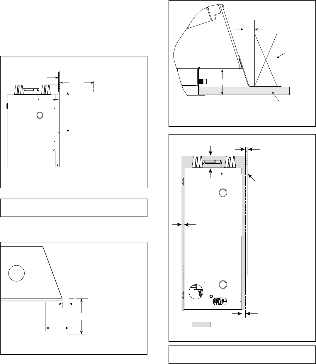
- C. Clearances 20
- 1-1/4 in. (30 mm) 21
- 1-1/2 in. (37 mm) 21
- TerminationLocations 22
- See note 2 23
- See note 3 23
- Effective 24
- INSTALLED 26
- HORIZONTALLY 26
- Max=44ft.(13.4m) 27
- NoElbows 27
- Note: Use SLP Series 28
- B. WallPenetrationFraming 31
- AppliancePreparation 34
- Appliance 35
- A. AssembleVentSections 36
- C. SecureTheVentSections 37
- B. AssembleSlipSections 37
- D. DisassembleVentSections 38
- Termination 40
- 1 in. (25 mm) 41
- 7-1/2 in 41
- (192 mm) 41
- GasInformation 42
- ElectricalInformation 44
- E.JunctionCordInformation 45
- Finishing 46
- Figure13.3FinishingDetails 47
- FIREPLACE OPENING 48
- 15-3/4 in. TO 16 in 48
- (400 mm TO 410 mm) 48
- C. FacingMaterial 50
- D. DecorativeFronts 52
- ApplianceSetup 53
- LOWER GLASS CLIP 53
- UPPER SPRING LATCH 53
- G. AirShutterSetting 54
- H. MediaOptions 54
- Troubleshooting 55
- ComponentAccess 58
- REMOVE SCREWS 58
- BURNER CLIP 58
- BASE PAN 58
- VALVEASSEMBLY 59
- G. GasValveReplacement 60
- 25 MM STANDOFF 61
- B.MaintenanceTasks 62
- C. VentComponentsDiagrams 63
- (178 mm) 65
- (305 mm) 65
- (133 mm) 66
- XLR-N-AU,XLR-PB-AU 67
- DONOTDISCARDTHISMANUAL 70
Relacionado con productos y manuales para Horno Heat-glo-fireplace HEAT & GLOW XLR-N-AU
 (40 paginas)
(24 paginas)
(40 paginas)
(24 paginas)
© 2020, manymanuals.es. Todos los derechos reservados | 0.052 s |
 Manymanuals.com
 Manymanuals.de
 Manymanuals.fr
 Manymanuals.it
 Manymanuals.pl
 Manymanuals.cz
 Manymanuals.es
 Manymanuals-pt.com
Comentarios a estos manuales